Mojotone Princeton Reverb Clone Project
On this page I explain the issues I had with my Princeton's 6V6 fixed
bias circuit and what I did to address them. The fixed bias circuit
is different from the cathode bias circuit used in the other tubes
in that the fixed bias circuit has its own power supply whose control
voltage is independent of the flow of current through the tube.
Initial bias measurements
When I initially checked the bias on the 6V6 tubes I found them to
be running "hotter" than I expected. The target power dissipation
for the JJ 6V6 is 70% of the maximum value of 14W, or 9.8W. Instead
I found that my 6V6 tubes were running over 12W. In fact, my measurements
showed:
| Item | 6V6 (brown wire) | 6V6 (blue wire) |
| center tap to plate voltage drop (Vdc) |
4.61 | 5.33 |
| plate (pin 3, Vdc) |
366 | 365 |
| grid (pin 5, Vdc) |
-26.6 | -26.7 |
| center tap to plate resistance (ohms) |
138.9 | 155.5 |
| current (amps) |
0.033189 | 0.034277 |
| power dissipation (watts) |
12.15 | 12.51 |
The full spreadsheet is here:
xlsx or
pdf
After some debugging and checking of the circuit, I decided that the bias
voltage on the grid of the 6V6 tubes was not negative enough resulting in
too much DC bias current flowing through the tubes. This resulted in the
tube power dissipation shown in the table above.
As describe here, the bias voltage
applied to the 6V6 grids is generated by the diode acting as a
half-wave rectifier in the DC bias supply circuit. The exact value of
the bias voltage is determined by the resistors in this circuit.
In particular, the 22K ohm resistor controls this voltage. When I
went back to check the DC bias power supply, I discovered that the
22K ohm resister I had was out of spec and actually measured 20.4K
ohms:
 The smaller the value of this resistor is, the closer the bias voltage
will be to zero volts (i.e. ground). The larger the the value of this
resistor is, the more negative the bias voltage will be. The -26 Vdc
bias voltage being applied to the grids of the 6V6 tubes resulted in
the 12W power dissipation shown above. Clearly the resistor needs to
have a larger value in order to get the power dissipation closer to
the target value of 9.8W.
The smaller the value of this resistor is, the closer the bias voltage
will be to zero volts (i.e. ground). The larger the the value of this
resistor is, the more negative the bias voltage will be. The -26 Vdc
bias voltage being applied to the grids of the 6V6 tubes resulted in
the 12W power dissipation shown above. Clearly the resistor needs to
have a larger value in order to get the power dissipation closer to
the target value of 9.8W.
Resistor substitution
To verify that the out-of-spec 22K resistor was an issue, I removed it
and used alligator clips to try different resistor values. The results:
| Resistor |
6V6 (brown wire, watts) | 6V6 (blue wire, watts) |
| 20.4K original resistor | 12.15 | 12.51 |
| 21.6K resistor | 10.76 | 10.90 |
| 26.6K resistor | 7.00 | 7.19 |
At this point I had two options: I could solder in a new resistor into the
bias power supply, or I could install a potentiometer in the bias power
supply. Adding a potentiometer is more work, but it makes it easier to
adjust the bias voltage in the future (e.g. when changing output tubes).
I decided to go with the potentiometer using one of Uncle Doug's
excellent videos
as a guide.
Bias potentiometer modification
The bias potentiometer modification is shown below:
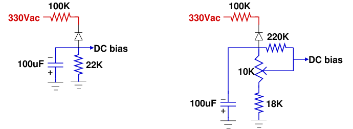 The AC voltage (shown in red) comes from the power transformer into
the 100K resistor and half-wave rectifier diode to convert it into
negative DC voltage (shown in blue). We remove the 22K resistor
and replace it with a 10K linear potentiometer in series with an
18K resistor. This allows us to have a base-level resistance of
18K and by adjusting the potentiometer we can add in as much or
as little of the 10K resistance in the potentiometer as we want (e.g.
from 18K to 28K which covers a good range of values from the 22K in
the original design).
In addition, we add a larger 220K resistor between the diode output
and the wiper of the potentiometer. Under normal use, the 220K
resistor is so much larger than the 10K and 18K resistors that it
has minimal impact on the circuit. But if the potentiometer has
mechanical issues and the potentiometer's wiper loses contact with
the rest of the potentiometer the 220K resistor provides an extra
voltage reference for the bias voltage to protect the output tubes
from losing their bias voltage and conducting too much current.
Note that no DC current flows out of the DC bias circuit since it
is just connected to the grids of the 6V6 tubes. The goal here
is to provide a negative bias voltage to the 6V6 grids.
The bias circuit is on the small board in the corner of the amp
near the pilot light. In the following figure, the 100K resistor
and diode are at the top of the figure, and the 22K resistor is
under the blue 100uF capacitor.
The AC voltage (shown in red) comes from the power transformer into
the 100K resistor and half-wave rectifier diode to convert it into
negative DC voltage (shown in blue). We remove the 22K resistor
and replace it with a 10K linear potentiometer in series with an
18K resistor. This allows us to have a base-level resistance of
18K and by adjusting the potentiometer we can add in as much or
as little of the 10K resistance in the potentiometer as we want (e.g.
from 18K to 28K which covers a good range of values from the 22K in
the original design).
In addition, we add a larger 220K resistor between the diode output
and the wiper of the potentiometer. Under normal use, the 220K
resistor is so much larger than the 10K and 18K resistors that it
has minimal impact on the circuit. But if the potentiometer has
mechanical issues and the potentiometer's wiper loses contact with
the rest of the potentiometer the 220K resistor provides an extra
voltage reference for the bias voltage to protect the output tubes
from losing their bias voltage and conducting too much current.
Note that no DC current flows out of the DC bias circuit since it
is just connected to the grids of the 6V6 tubes. The goal here
is to provide a negative bias voltage to the 6V6 grids.
The bias circuit is on the small board in the corner of the amp
near the pilot light. In the following figure, the 100K resistor
and diode are at the top of the figure, and the 22K resistor is
under the blue 100uF capacitor.

The 10K linear pot used in Fender-style amps is show below. To adjust it,
you put a screwdriver down in the hole and turn the wiper. This design
prevents you from accidently changing the bias adjustment.
 To secure the pot to the chassis I used a piece of sheet metal I
got from the Home Depot. I made a mounting bracket by cutting the
sheet metal with tin snips, using a vice to bend it to the desired
shape, and drilling out holes in which to attached the bracket to
one of the power transformer screws and the pot.
To secure the pot to the chassis I used a piece of sheet metal I
got from the Home Depot. I made a mounting bracket by cutting the
sheet metal with tin snips, using a vice to bend it to the desired
shape, and drilling out holes in which to attached the bracket to
one of the power transformer screws and the pot.


Once the mounting bracket was complete I was able to install the pot in
the amp by screwing down the bracket and soldering it in I used a marker
on the bracket to indicate what direction to turn the pot's wiper to make
the 6V6 tubes hotter.


 Having successfully installed the bias pot, I adjusted its value to get
the power dissipation of the 6V6 tubes to its current value of around 10W.
See the testing page to see the
current bias measurements.
Having successfully installed the bias pot, I adjusted its value to get
the power dissipation of the 6V6 tubes to its current value of around 10W.
See the testing page to see the
current bias measurements.
Amp warmup impact on measuring bias
One thing to be aware of when using the resistance of the output transformer
winding to compute the tube current is that this resistance is not constant.
As the amp warms up, the resistance of the output transformer increases.
So it is best to try to take your voltage and resistance measurements at
about the same time so that they match the current temperature of the amp.
To test this, I started with a cold amp and measured the output transformer
resistance at 1 minute, 5 minutes, 10 minutes, 15 minutes, and 20 minutes
of operation. The results are in the following table.
| Transformer side | 1 minute | 5 minutes |
10 minutes | 15 minutes | 20 minutes |
| brown wire (ohms) |
133.8 | 136.7 | 138.4 | 140.1 | 141.6 |
| blue wire (ohms) |
149.9 | 153.9 | 156.4 | 157.3 | 158.5 |
Return to main page
This page maintained by Chuck Cranor