")
")
 120 Vac power is supplied to the amplifier through the mains power cord.
The mains current is routed through the fuse and power switch into
the primary winding of the power transformer. Current in the primary
winding of the transformer generates AC voltage on the secondary side
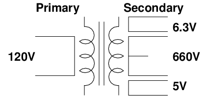
of the transformer. The secondary side of the power transformer has
three taps: a 5 Vac supply for the rectifier, a 6.3 Vac supply for
heating the filaments of the preamp and power tubes, and a 660 Vac
high voltage supply for the rest of the amp. The 660 Vac windings
on the secondary side of the power transformer have a center tap
that we can connect to ground to provide us with two 330 Vac supplies.
The next two figures show the 5 Vac and 6.3 Vac, respectively.
With no load on the power supply the 5 Vac supply measures 5.45 Vac
and the 6.3 Vac supply measures 6.82 Vac.
120 Vac power is supplied to the amplifier through the mains power cord.
The mains current is routed through the fuse and power switch into
the primary winding of the power transformer. Current in the primary
winding of the transformer generates AC voltage on the secondary side
of the transformer. The secondary side of the power transformer has
three taps: a 5 Vac supply for the rectifier, a 6.3 Vac supply for
heating the filaments of the preamp and power tubes, and a 660 Vac
high voltage supply for the rest of the amp. The 660 Vac windings
on the secondary side of the power transformer have a center tap
that we can connect to ground to provide us with two 330 Vac supplies.
The next two figures show the 5 Vac and 6.3 Vac, respectively.
With no load on the power supply the 5 Vac supply measures 5.45 Vac
and the 6.3 Vac supply measures 6.82 Vac.
") The next two figures show the high voltage power supply using 100x probes.
The first figure shows the voltage between the two ends of the power
supply (note that the scale is 500V per block). With no load we see 675 Vac.
The next figure (at scale 200V per block) shows the two legs of the high
voltage supply with the ground at the center tap. The legs roughly
measure 345 Vac.
The next two figures show the high voltage power supply using 100x probes.
The first figure shows the voltage between the two ends of the power
supply (note that the scale is 500V per block). With no load we see 675 Vac.
The next figure (at scale 200V per block) shows the two legs of the high
voltage supply with the ground at the center tap. The legs roughly
measure 345 Vac.
")
") The next two plots shows the voltages at the ends of high-voltage windings
and the 6.3 Vac supply winding with respect to ground.
The next two plots shows the voltages at the ends of high-voltage windings
and the 6.3 Vac supply winding with respect to ground.
")
")
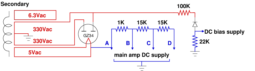 The secondary side of the power transformer provides has three AC taps.
The AC circuits are shown in red in the figure above. The 6.3Vac circuit
provides power for the pilot light and the heaters for all the tubes
except the rectifier tube. Both legs of the 6.3Vac circuit are wired
through a 100 ohm resistor to the chassis ground (not shown in the figure).
This connection is to provide a voltage reference to chassis ground
and ensure that the two legs are properly out of phase to cancel out
hum (the AC current does not flow to ground).
The 5Vac circuit is for heating the filament of the GZ34 rectifier tube.
The AC current flows from one side of the 5Vac tap on the power transformer
through the GZ34 and back to the other side of the 5Vac tap.
The high voltage 660Vac windings on the secondary side of the power
transformer have a center tap connected to the chassis ground. This
results in the 660Vac voltage being divide into two 330Vac supplies
with respect to the chassis ground. The two 330Vac supplies are 180
degrees out of phase with each other. This can be seen in the oscilloscope
plots above.
The secondary side of the power transformer provides has three AC taps.
The AC circuits are shown in red in the figure above. The 6.3Vac circuit
provides power for the pilot light and the heaters for all the tubes
except the rectifier tube. Both legs of the 6.3Vac circuit are wired
through a 100 ohm resistor to the chassis ground (not shown in the figure).
This connection is to provide a voltage reference to chassis ground
and ensure that the two legs are properly out of phase to cancel out
hum (the AC current does not flow to ground).
The 5Vac circuit is for heating the filament of the GZ34 rectifier tube.
The AC current flows from one side of the 5Vac tap on the power transformer
through the GZ34 and back to the other side of the 5Vac tap.
The high voltage 660Vac windings on the secondary side of the power
transformer have a center tap connected to the chassis ground. This
results in the 660Vac voltage being divide into two 330Vac supplies
with respect to the chassis ground. The two 330Vac supplies are 180
degrees out of phase with each other. This can be seen in the oscilloscope
plots above.
| circuit | No tubes installed (Vac) | Rectifier only (Vac) | All tubes installed (Vac) |
|---|---|---|---|
| rectifier heater (pin 2 to 8) | 5.36 | 5.20 | 5.02 |
| heaters (pins 4 and 5 to 9) | 6.76 | 6.76 | 6.26 |
| high voltage (GZ34 pin 4 to ground) | 335 | 335 | 321 |
| high voltage (GZ34 pin 6 to ground) | 335 | 335 | 321 |
| Node | Rectifier only (Vdc) | All tubes installed (Vdc) |
|---|---|---|
| A | 466 | 392 |
| B | 466 | 381 |
| C | 465 | 310 |
| D | 465 | 257 |
| circuit location | No tubes installed (Vdc) | Rectifier only (Vdc) | All tubes installed (Vdc) |
|---|---|---|---|
| input to 100K resistor | -0.016 | -0.016 | -0.017 |
| input to diode | 129.4 | 129.7 | 122 |
| output of diode | -38.0 | -37.9 | -36.7 |
| 6V6 grids (pin 5) | -32.3 | -32.1 | -31 |
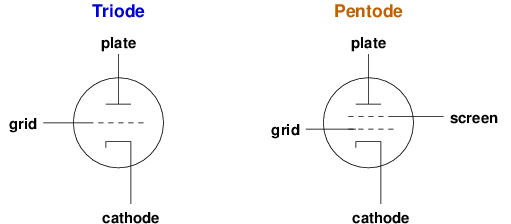 Tubes in the Princeton amp are biased in one of two ways. The 12AX7s
and 12AT7 are cathode biased. At a high-level this means
that the cathode is connected to a resistor and the other end of
that resistor is connected to a point in common with the grid (often
ground). This causes the voltage at the cathode to be higher than
the voltage at the grid thus giving us our bias voltage. The larger
the resistor is, the greater the bias voltage is and the less current
will flow through the tube. Note that there may also be a capacitor
connected to the cathode, but since capacitors block DC current they
will have no impact on the bias voltages.
The other way tubes are biased in the Princeton amp is fixed bias
The two 6V6 power tubes use this type of bias. In the Princeton
fixed bias circuit the cathodes of the power tubes are connected
directly to ground and an
independent power supply is used to apply a negative voltage to the
grid. (Since the cathode is tied to ground at zero volts, the
grid voltage must be less than this to control the tube's power
dissipation.) The DC bias voltage is supplied by
the diode in the half-wave rectifier discussed earlier. The 22K
resistor controls the value of the DC bias voltage. If this resistor
is made larger, the DC bias voltage will become more negative with
respect to the cathode and the DC bias current will be reduced.
Reducing the value of the 22K resistor will have the opposite effect
(i.e. it will make the tube run hotter). In the Fender Princeton
amp design, the only way to change the bias voltage on the 6V6 tubes
is to replace the 22K resistor with a resistor with a different
value. To make the bias easier to adjust, you can replace the
22K resistor with a circuit that contains a potentiometer that
changes the resistance (I made this change to my amp).
Tubes in the Princeton amp are biased in one of two ways. The 12AX7s
and 12AT7 are cathode biased. At a high-level this means
that the cathode is connected to a resistor and the other end of
that resistor is connected to a point in common with the grid (often
ground). This causes the voltage at the cathode to be higher than
the voltage at the grid thus giving us our bias voltage. The larger
the resistor is, the greater the bias voltage is and the less current
will flow through the tube. Note that there may also be a capacitor
connected to the cathode, but since capacitors block DC current they
will have no impact on the bias voltages.
The other way tubes are biased in the Princeton amp is fixed bias
The two 6V6 power tubes use this type of bias. In the Princeton
fixed bias circuit the cathodes of the power tubes are connected
directly to ground and an
independent power supply is used to apply a negative voltage to the
grid. (Since the cathode is tied to ground at zero volts, the
grid voltage must be less than this to control the tube's power
dissipation.) The DC bias voltage is supplied by
the diode in the half-wave rectifier discussed earlier. The 22K
resistor controls the value of the DC bias voltage. If this resistor
is made larger, the DC bias voltage will become more negative with
respect to the cathode and the DC bias current will be reduced.
Reducing the value of the 22K resistor will have the opposite effect
(i.e. it will make the tube run hotter). In the Fender Princeton
amp design, the only way to change the bias voltage on the 6V6 tubes
is to replace the 22K resistor with a resistor with a different
value. To make the bias easier to adjust, you can replace the
22K resistor with a circuit that contains a potentiometer that
changes the resistance (I made this change to my amp).
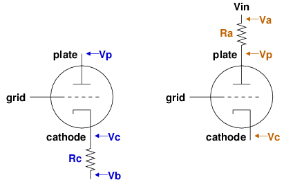 In all cases we use three voltage measurements and one resistance value
to compute the power dissipation. For cathode biased tubes it is
convenient to use the cathode resistor Rc value to compute the DC
current (note that any capacitor in parallel with resistor can
be ignored because it should not be carrying any DC current). Thus
we use the blue values on the left side of the figure to compute the
power dissipation like this:
In all cases we use three voltage measurements and one resistance value
to compute the power dissipation. For cathode biased tubes it is
convenient to use the cathode resistor Rc value to compute the DC
current (note that any capacitor in parallel with resistor can
be ignored because it should not be carrying any DC current). Thus
we use the blue values on the left side of the figure to compute the
power dissipation like this:
| Item | 12AX7(1) | 12AX(2) | 12AT7 | 7025 |
|---|---|---|---|---|
| Triode (T1) purpose | vibrato lfo | reverb recovery | reverb | input preamp |
| T1 plate (pin 1, Vdc) | 227 | 167 | 337 | 164.7 |
| T1 grid (pin 2, Vdc) | 0 | 0 | 0 | 0 |
| T1 cathode (pin 3, Vdc) | 2.27 | 1.36 | 7.35 | 1.347 |
| T1 cathode resistor (ohms) | 3300 | 1500 | 2200 | 1500 |
| T1 cathode resistor voltage (far end, Vdc) | 0 | 0 | 0 | 0 |
| T1 current (amps) | 0.000688 | 0.000907 | 0.001670 | 0.000898 |
| T1 power dissipation (watts) | 0.155 | 0.150 | 0.617 | 0.147 |
| Item | 12AX7(1) | 12AX(2) | 7025 |
|---|---|---|---|
| Triode (T2) purpose | inverter | mixer | after volume pot |
| T2 plate (pin 6, Vdc) | 236 | 165.4 | 171.7 |
| T2 grid (pin 7, Vdc) | 17.9 | 0 | 0 |
| T2 cathode (pin 8, Vdc) | 70.6 | 1.448 | 1.302 |
| T2 cathode resistor (ohms) | 1000 | 1500 | 1500 |
| T2 cathode resistor voltage (far end, Vdc) | 69.7 | 0.0447 | 0 |
| T2 current (amps) | 0.000900 | 0.000936 | 0.000868 |
| T2 power dissipation (watts) | 0.149 | 0.153 | 0.148 |
| Item | 6V6 (brown wire) | 6V6 (blue wire) |
|---|---|---|
| center tap to plate voltage drop (Vdc) | 3.70 | 4.15 |
| plate (pin 3, Vdc) | 386 | 386 |
| screen (pin 4, Vdc) | 381 | 381 |
| grid (pin 5, Vdc) | -31.3 | -31.3 |
| cathode (pin 8, Vdc) | 0 | 0 |
| center tap to plate resistance (ohms) | 142.1 | 159.1 |
| current (amps) | 0.026038 | 0.0260842 |
| power dissipation (watts) | 10.051 | 10.069 |