Mojotone Princeton Reverb Clone Project
Return to main page
Here is a log of how I assembled the amp. The Mojotone kit does
not include any assembly instructions, so you have to plan out
all the steps yourself.
Drill chassis mounting holes in cabinet
There are four long screws that are used to mount the chassis in
the cabinet, but the cabinet does not come with the holes drilled.
I decided to drill these holes first, before installing anything
heavy in the chassis. The chassis fits into the cabinet like this:
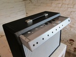
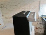
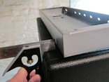
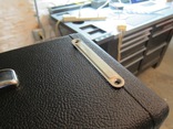
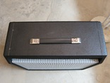
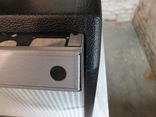 Finding the right place for the holes is a bit tricky because
the front end of the cabinet and chassis is sloped. I used a
ruler, the metal straps, and the chassis itself as a guide to
mark the drilling location for the holes. I decided that it would
be easier to measure from the back of the cabinet (to avoid the slope).
I used a 11/64" bit to drill the initial holes and then later
used a 3/16" bit to widen them out a bit.
Install tube sockets
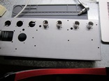
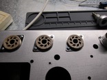
Next I installed the 3 large and 4 small tube sockets using
4-40 3/8" and 4-40 1/4" screws, respectively. Make sure
pin 1's position matches the wiring diagram. (I forgot to
put the retaining springs on the 3 big tube sockets and had
to go back and add them later.)
Install power transformer
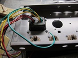
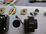
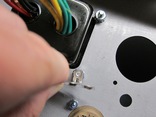
I installed the power transformer using 4 8-32 nuts, keeping the
transformer label pointed towards the back to make it easier to see
when the chassis is installed in the cabinet. I also looked at
installing a ground terminal on the power transformer screw, but
discovered that the screw is too big to fit through the hole
on the 3 lug terminal strip.
Install output and reverb transformers
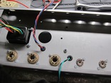
Next, I installed the output and reverb transformers using grommets
and 8-32 3/8" screws and nuts. I also went back and installed the
retaining springs for the 3 big tube sockets.
Install cap can
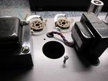
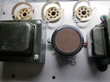
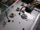
The chassis holes for mounting the cap can clamp are the same size as
the holes for mounting the tube sockets, so the biggest screw that fits
is the 4-40. Unfortunately Mojotone only provides enough 4-40 screws
and nuts for the tube sockets, so I ended up going to Home Depot and
buying 2 more 4-40 3/8" screws and nuts (the first figure below shows
how the next largest size screw will not fit through the hole).
Once I had new the screws and nuts I was able to install the cap can.
Install pots
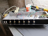
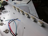
Next I installed the pots in the chassis. One of the tone pots
was missing a flat washer, so I contacted Mojotone and they sent
me the missing washer.
Install input jacks and pilot light
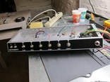
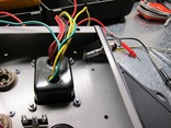
I installed the instrument jacks and pilot light next (they'll
have to be removed when their wiring is installed). I was a
bit concerned about the pilot light assembly shorting out on
the chassis, so I later added some black electrical tape to
further insulate it (see further below).
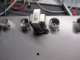
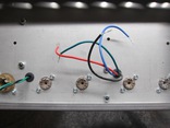
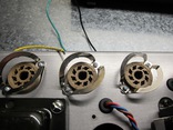
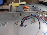
Install RCA jacks for reverb and footswitch
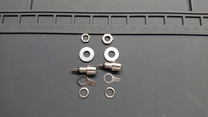
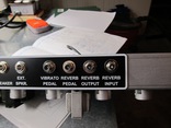
Next I attempted to install the RCA jacks for the reverb tank
and footswitch. Unfortunately, Mojotone included the wrong type
of RCA jacks in their parts kit, so I had to get them to send me
replacements. The screw threads for the RCA jack should be set up
so that you install the nut that holds the jack to the chassis from
the outside of the chassis, not the inside. Otherwise you won't
be able to get enough of the threads through to get the nut on
securely. The first picture below shows the wrong RCA jacks, while
the second two pictures show the replacement RCA jacks properly
installed.
Populate eyelet boards
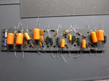
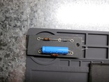
Next, I populated the main and bias outlet boards with resistors,
capacitors, and diodes.
Part check once eyelet boards are done
Once the eyelet boards are populated, the following resistors
and capacitors should be remaining in the parts box:
- 1 .047 uf orange cap: the "death" cap (unlikely to use this)
- 2 100 ohm resistors: virtual center tap for heaters (off pilot light)
- 1 6.8K ohm resistor: basss tone control
- 1 15K 2W ohm resistor: on the cap can
- 2 68K ohm resistors: for input jacks
- 1 100K ohm resistor: speed pot
- 1 220K ohm resistor: reverb pedal jack on back to ground
- 1 1M ohm: for input jack circuit
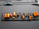
Reduce main eyelet board lead count
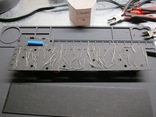
Some of the eyelets in the main board were over-stuffed with wires.
For example, the eyelet in the top middle of the board had 6 leads
going into it. To reduce this, I decided to solder the leads of each
cathode bias resistor directly to the leads of its cathode bypass
capacitor rather than running it through the eyelet (the cathode
bypass capacitors are the black caps seen in the picture).
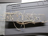
Solder wires onto main eyelet board
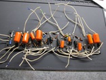
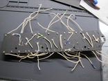
Next I soldered all the needed connection wires to the eyelet board.
To do this, I estimated the length of each wire and then soldered it
in. When multiple wires used the same route, I used a marker on
the white cloth to color code them to ensure that I made the proper
connections. I trimmed off the extra leads on the back of the
board as I soldered in components.
Add flyover power wires to main eyelet board
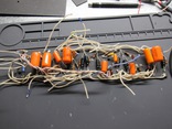
I installed all the flyover power wires next. These wires carry
DC power from the power supply nodes B, C, and D on the left side
of the board to the right side. I used a marker to color code
the cloth wires: B=red, C=black, D=blue. The wire marked X in
the wiring diagram is also in flyover bundle (I left it white).
(In pictures of old Fender amps B=red, D=yellow, X=white and
C is not used). Once this is done, only two eyelets should
be left unsoldered: these are where the red wires from the output
and reverb transformer connect.
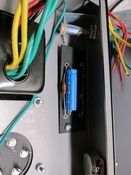
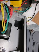
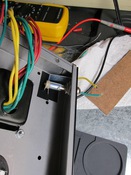
Drill and solder bias eyelet board, insulate chassis under pilot light
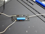
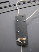
Next I worked on the bias eyelet board and pilot light. I put
the bias eyelet board in place to mark where I needed to drill in it
in order to put in the mounting screws (I used an 11/64" bit). I also
added tape to the area where the pilot light comes close to the
chassis to ensure that it doesn't short out on the chassis. I then
soldered all the leads to the bias eyelet board.
Build instrument input circuit
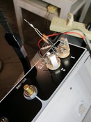
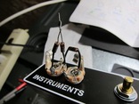
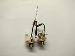
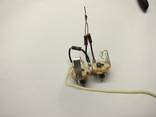
I flipped the input jacks around to the outside of the chassis so
that I could use the holes in the chassis as as guide to assemble
the input circuit. I used heat shrink tube on the resistor wires
to protect the circult. I also added a ground wire to the input
circuit to connect the ground on the pots.
Install grounding bus and lug
The diagrams provided by Mojotone leave the details of the amp's
grounding scheme up to the builder. A poor choice of grounding
scheme may lead to a noisy amplifier (e.g. due to ground loops).
After researching grounding, I decided to use the grounding scheme
described here:
http://el34world.com/charts/grounds.htm.
For this grounding scheme, you solder a grounding bus across the
back of the pots and connect it to the input circuit (the input
circuit is grounded to the chassis). The power supply is grounded
to a 3 lug terminal strip I installed near the power transformer.
The two end lugs are connected to the center lug, so all three lugs
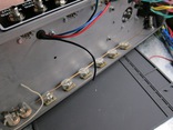
are grounds. The picture below shows the ground bus soldered to
the back of the pots. I used the ground wire from a 14-2 romex
power cable for the ground bus.
Screw main eyelet board to chassis
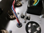
Next, I screwed the main eyelet board onto the chassis using
3 6-32 screws and nuts. I had to loosen the output transformer
to get one of the screws in. I had to drill holes in the backing
board for the screws to go through (maybe I should have done this
before installing all the parts).
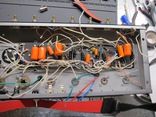
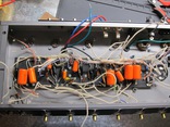
Solder input and pots to eyelet board
I soldered in the input circuits, the pots, and the ground
connections from the main eyelet board to the ground bus
on the pots.
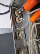
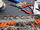
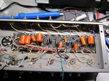
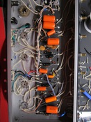
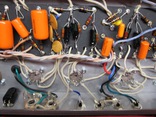
Solder preamp tubes, speaker/RCA jacks, reverb/output transformers
Next, I soldered in the 9 pin tube sockets, starting with the first
7025/12AX7 preamp tube. I also soldered the reverb and output
transformers. The black (ground) wire from the reverb transformer
is not shown on the Mojotone wiring diagram (it goes to the RCA
jack shown in the figure).
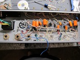
Solder power tubes and cap can
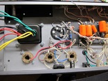
Here I've soldered in the cap can, and the 6V6 output tube sockets.
Solder power transformer rectifier circuits
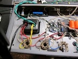
Next I soldered in the 5V and high voltage secondary leads of
the power transformer (the red/yellow wire is the grounded center tap
of the high voltage circuit).
Twist heater wire and install to pilot light
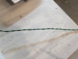
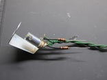
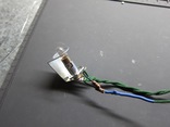
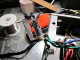
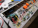
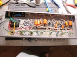
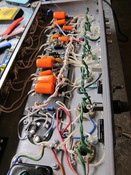
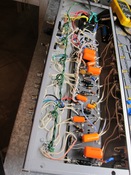
I twisted the green wire together for the 6.3V heater circuit, and
then I attached it to the pilot light along with the 2 100 ohm resisters
that form the virtual center tap for the heater circuit. Then I
soldered the whole assembly to the 6.3V feed from the power transformer
and reinstalled the pilot light.
Install heater power wires to all sockets
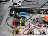
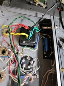
Next I soldered in the twisted 6.3V heater wires into all
the tube sockets. The green wire is twisted and kept
above and apart from the other wires to avoid unwanted
AC power noise.
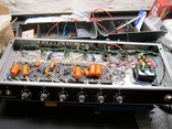
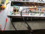
Install 3 prong mains power cord
I installed the 3 prong AC mains power cord. The black
hot wire goes from the cord to the fuse and then to the
power switch. From the power switch it goes into the
primary winding of the power transformer and returns
through the white neutral wire. The green ground wire
from the plug has its own connection to the chassis through
one of the screws on the power transformer.
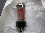
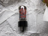
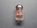
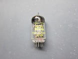
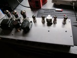
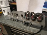
Remove tubes from box and install
I removed the tubes from their boxes and checked their fit in
the tube sockets by installing them. I later removed them before
powering up the amp for the first time
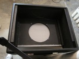
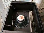
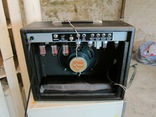
Install speaker wire and speaker in cabinet
I twisted together the black and white stranded wire and installed
the 1/4" jack on the end. I then installed the speaker in the cabinet
and put the chassis in the cabinet to verify that everything still fit.
Next steps
The amp is now ready for testing before final assembly!
Return to main page
This page maintained by Chuck Cranor


 Finding the right place for the holes is a bit tricky because
the front end of the cabinet and chassis is sloped. I used a
ruler, the metal straps, and the chassis itself as a guide to
mark the drilling location for the holes. I decided that it would
be easier to measure from the back of the cabinet (to avoid the slope).
I used a 11/64" bit to drill the initial holes and then later
used a 3/16" bit to widen them out a bit.


