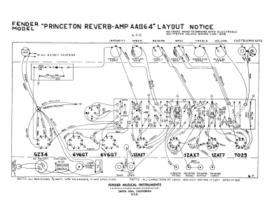
Overview and schematics
The Fender Princeton Reverb guitar amp was first sold in 1964. Prior to
this, Fender produced and sold a Princeton amp without reverb.
From 1964 to 1967 the Princeton Reverb had blackface cosmetics.
In 1968 Fender changed the Princeton Reverb into a silverface amp.
Overview
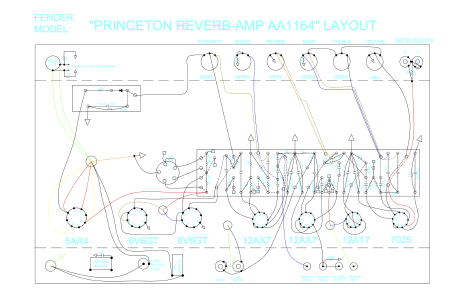
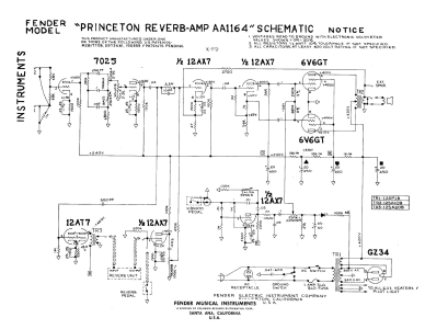
Princeton Reverb amps have 7 tubes: a rectifier, two output tubes,
and four preamp tubes. The Mojotone kit comes with a GZ34 rectifier
and 2 6V6S output tubes. The reverb is driven by a 12AT7 preamp tube,
while the rest of the preamp tubes are 12AX7s. The amp has a single
volume control, a treble and base control for the tone stack, and
then for on-board effects it has reverb-level and tremolo speed and
intensity. The speaker is a 10" Jensen C10Q.
Schematics and wiring diagrams
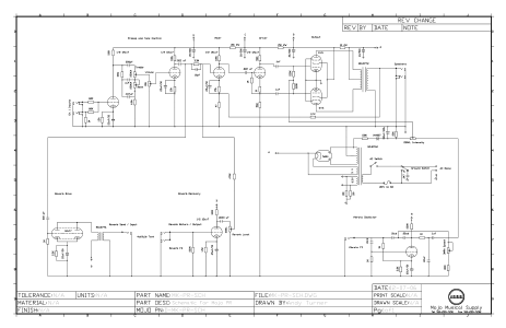
Click the images for larger PDF versions of the diagrams. The Mojotone
schematic shows the core of the amplifier circuit across the top of the
page with the input and preamp on the left and the output and speaker on
the right. The reverb section is on the bottom left side of the figure.
The tremolo is on the bottom right side of the figure, and the power supply
is above it. The Mojotone wiring diagram uses a light blue font that
prints ok, but is hard to read on a computer screen (the blue is too
light).
Notes
I found it useful to print these diagrams on larger sheets of
paper (e.g. 11x17) to make it easier to read and make notes on.
The Mojotone circuit does not exactly match the 1964 Fender circuit.
Some of the Mojotone components have been made more robust (e.g.
the cap on the bias board is 100V instead of 50V), and the inverter
triode's plate runs off node C of the power supply instead of node D
(a common mod).
The Mojotone diagrams have the shortcoming of not including the
expected voltage values at various points in the circuit like the
Fender diagrams do. This is aggravating as the Mojotone circuit
is not an exact match of the Fender circuit, so the voltages in
the new design may differ.
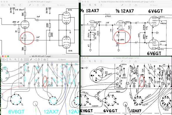
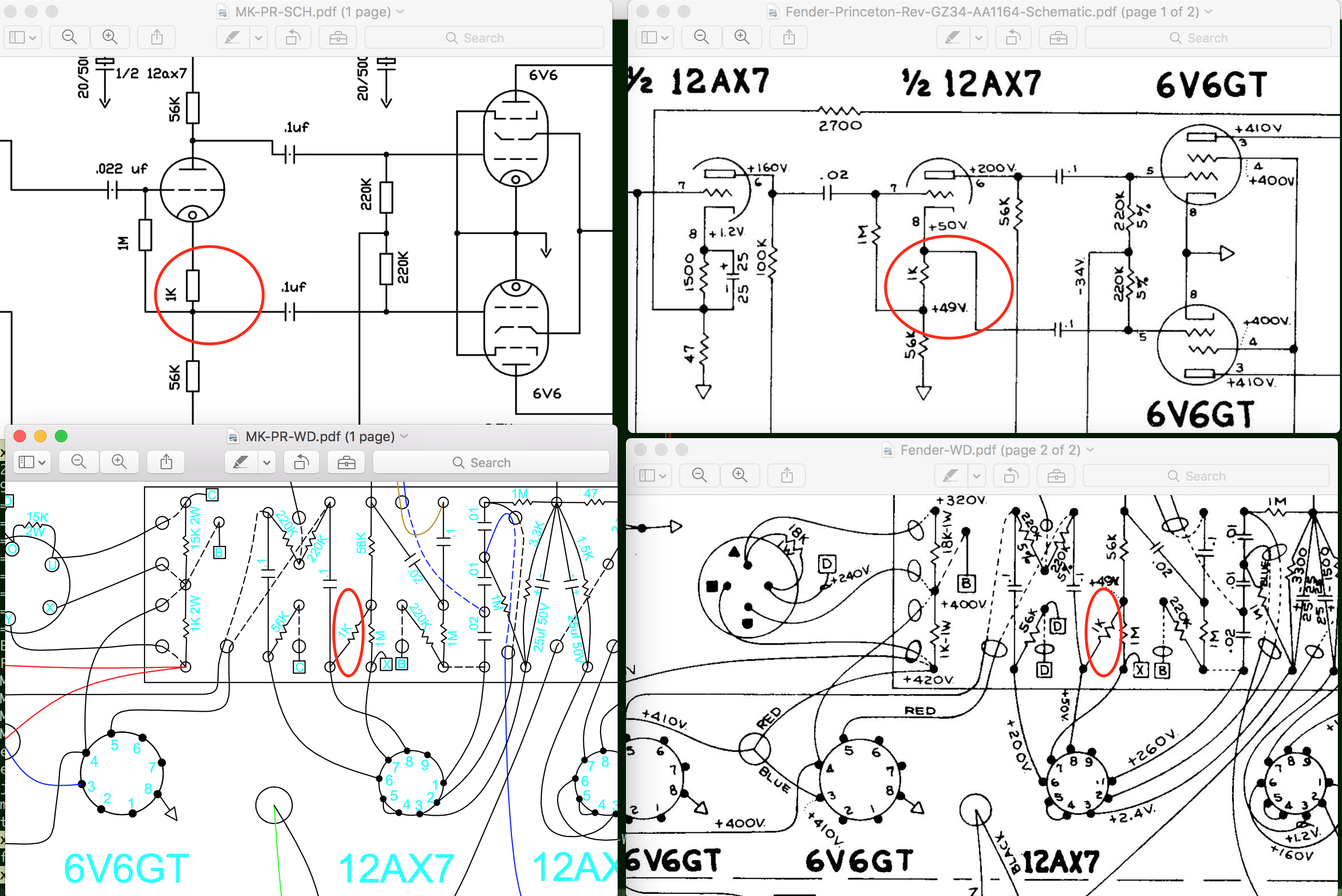
The version of the Mojotone schematic on their web page has
an error. The connection from the phase inverter cathode to the grid
of the lower 6V6 power tube should attach above the 1K ohm resistor, not
below it. The figure below shows the issue by comparing the Mojotone
drawings (on the left) to the Fender versions (on the right). The
error is in the drawing on the top left... this figure doesn't match
the other 3. I've reported the error, so hopefully the version on
the Mojotone web site will eventually get fixed.
 Return to main page
This page maintained by Chuck Cranor
 Return to main page